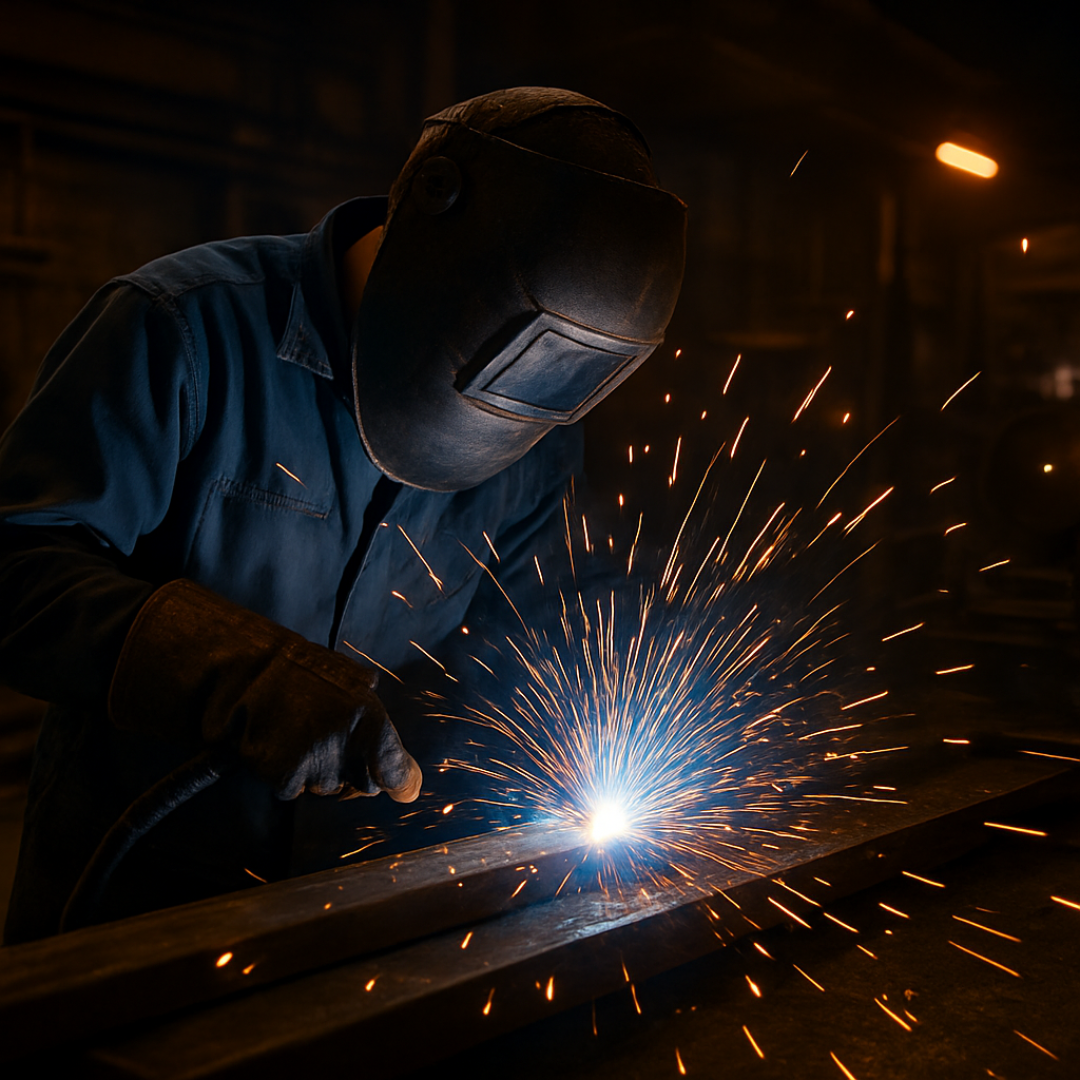
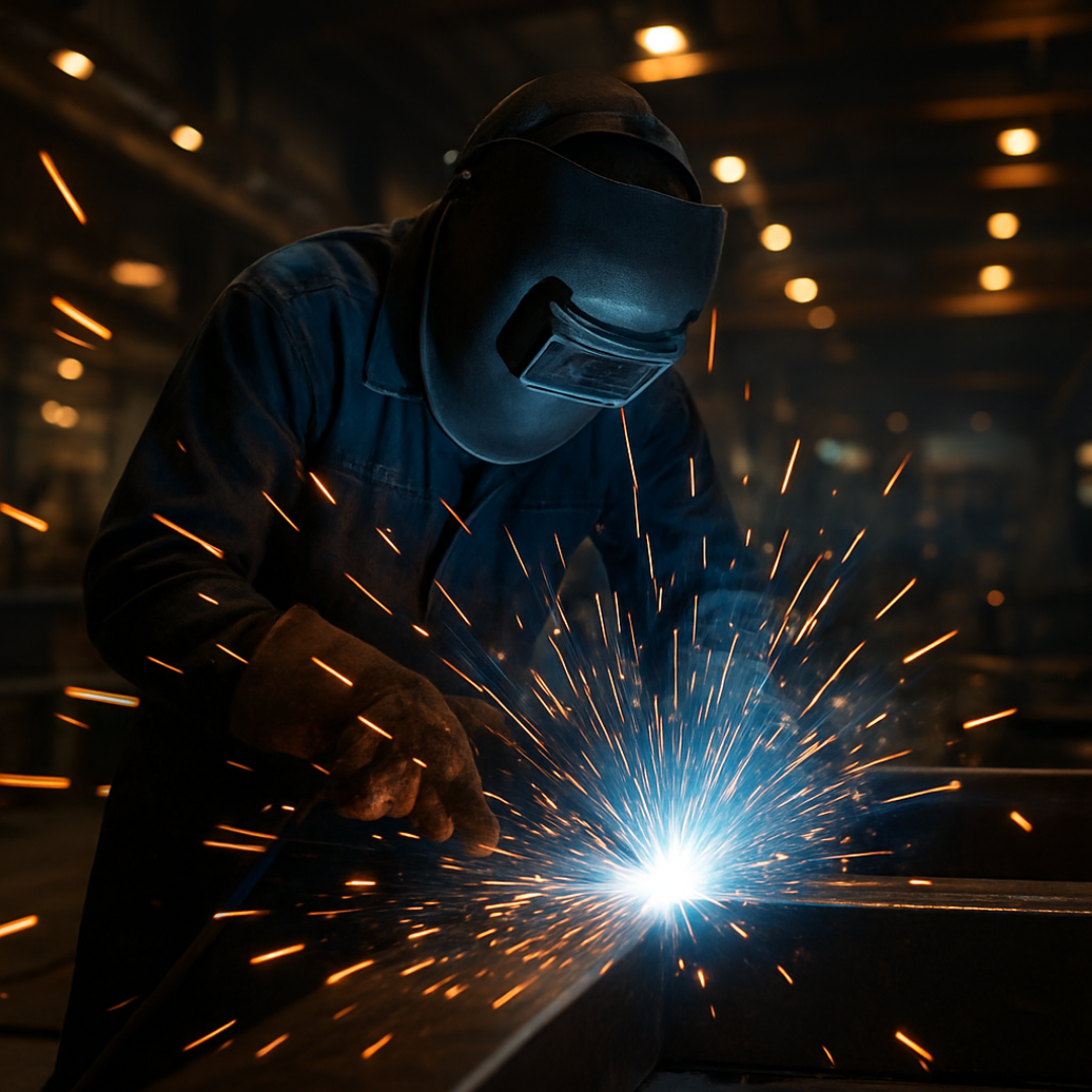
A welding terminology guide serves as your essential roadmap to understanding the specialized language used across welding shops, manufacturing facilities, and construction sites. Whether you’re a beginner picking up your first electrode or an experienced fabricator looking to refine your knowledge, mastering these terms transforms confusion into confidence and helps you communicate effectively with fellow welders, inspectors, and engineers.
Welding encompasses 93 distinct techniques recognized by the American Welding Society, each carrying its own vocabulary that can feel overwhelming at first glance. But here’s the truth: once you grasp the fundamental terminology, everything else falls into place naturally. This guide breaks down the complex jargon into digestible sections, helping you navigate conversations about beads, penetration, heat-affected zones, and everything in between.
Understanding Core Welding Terminology
The foundation of welding knowledge rests on understanding basic concepts that appear repeatedly in every welding conversation.
The Building Blocks: Essential Welding Terms
Bead represents the visible result of your welding work—a continuous line where fused metal creates a solid connection between two pieces. Every weld produces this characteristic bead, revealing your technique quality.
Penetration describes how deeply the molten weld metal burns into the base metal or previous passes. Proper penetration ensures structural integrity, while insufficient penetration creates weak joints prone to failure.
Heat-affected zone (HAZ) identifies the area surrounding your weld that hasn’t melted but has undergone metallurgical changes from high temperatures. This zone matters because molecular structure changes can affect metal properties and create weak spots.
The weld pool or puddle refers to that glowing, molten portion of metal you control during welding. Watching and manipulating this pool separates skilled welders from novices.
Parent metal or base metal means the main material you’re joining together. This terminology helps distinguish between the original material and the filler metal you’re adding.
Understanding Electrodes and Filler Materials
Electrodes conduct electricity to create the welding arc. A consumable electrode melts during welding and contributes to the weld itself, used in MIG, stick, and flux-core welding. A non-consumable electrode like tungsten in TIG welding initiates and maintains the arc without melting, requiring separate filler metal when needed.
Filler metal provides additional material to complete the joint and achieve desired weld properties. Different applications demand specific filler metals—matching base metal composition or adding properties like corrosion resistance.
Flux shields molten metal from atmospheric contamination and oxidation. In stick welding, flux coats the electrode and creates protective slag. Flux-core wires carry flux internally, while submerged arc welding uses granular flux that blankets the weld zone.
Shielding gas accomplishes similar protection through different means. Inert gases like argon don’t react with molten metal, while active gases like carbon dioxide can interact with weld chemistry.

Welding Processes Decoded
Understanding different welding processes requires familiarity with their specific terminology.
Arc Welding Methods
Gas Metal Arc Welding (GMAW) or MIG welding uses a solid wire electrode continuously fed through a welding gun while shielding gas protects the weld. This semi-automatic process dominates manufacturing and custom fabrication because of its speed and ease of learning.
Gas Tungsten Arc Welding (GTAW) or TIG welding employs a non-consumable tungsten electrode and offers exceptional heat control. The welder manually feeds filler rod when needed, creating pristine welds on stainless steel and aluminum where quality matters most.
Shielded Metal Arc Welding (SMAW) or stick welding uses flux-coated consumable rods. Despite being one of the oldest methods, it remains invaluable for construction and repair work because it tolerates wind, dirt, and challenging conditions.
Flux-cored Arc Welding (FCAW) splits into two categories: FCAW-G uses external shielding gas, while FCAW-S is self-shielded, making it perfect for outdoor construction where wind would blow away protective gas.
Submerged Arc Welding (SAW) operates beneath a blanket of granular flux, creating high-quality welds with impressive deposition rates for heavy structural manufacturing work.
Other Welding Techniques
Resistance welding generates heat through electrical resistance. Spot welding joins sheet metal at specific points, seam welding creates continuous joints along edges, and projection welding uses specially designed electrodes. These methods dominate automotive manufacturing.
Gas welding, particularly oxy-acetylene welding, uses fuel gas and oxygen to create flames that melt metal. Though largely replaced by arc welding, it remains useful for brazing and repair tasks requiring precise heat control.
Welding Positions and Joint Types Explained
Position terminology helps welders and engineers communicate exactly how a weld should be performed.
Standard Welding Positions
Welding positions combine numbers with letters—”G” indicates groove welds, while “F” denotes fillet welds.
Flat position (1G, 1F) places the workpiece horizontally with weld metal deposited on the upper surface, allowing gravity to assist rather than hinder work.
Horizontal position (2G, 2F) orients the workpiece vertically while the welder moves horizontally across it, requiring technique adjustments to prevent sagging.
Vertical position (3G, 3F) runs the weld axis vertically, progressing upward for deeper penetration or downward for faster travel on thin materials.
Overhead position (4G, 4F) puts the workpiece above the welder, creating the most challenging position where gravity constantly pulls molten metal downward.
Pipe Welding Positions
Horizontal rolled position (1G) allows pipe rotation so welding occurs in the flat position throughout. Vertical fixed position (2G) holds the pipe vertically without rotation while welding horizontally around it.
Horizontal fixed position (5G) keeps pipe stationary and nearly level, requiring welding from top downward or bottom upward. Inclined fixed position (6G) sets pipe at 45 degrees without rotation, presenting the ultimate welding challenge.
Joint Configurations
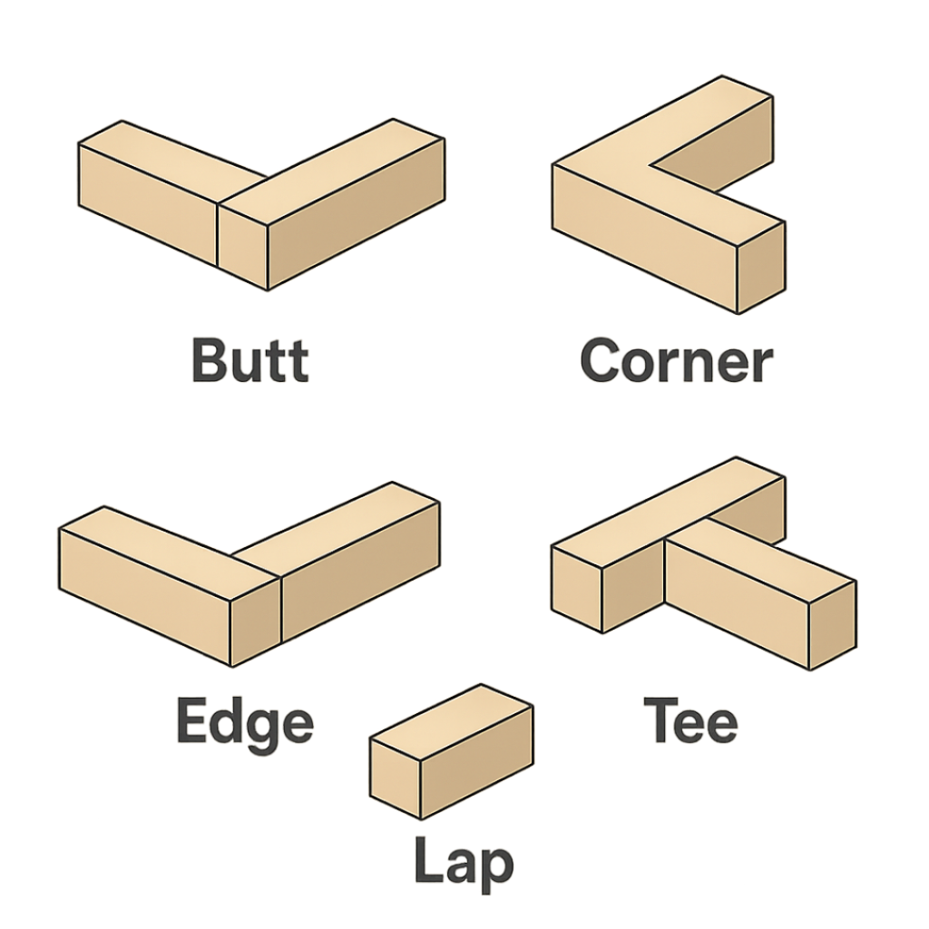
Butt joints place two pieces end-to-end. Corner joints bring pieces together at angles, typically 90 degrees. Edge joints align sheets for welding along outer edges. Lap joints stack one plate on another, welding where they overlap. Tee joints position one plate perpendicular to another, forming a T-shape.
Critical Joint Preparation Terms
Proper joint preparation determines weld quality before striking the first arc.
Bevel refers to the angled edge preparation ensuring adequate penetration on thicker materials, with different angles suiting different applications.
Root opening or gap describes the deliberate space between pieces being joined, varying based on welding process, material thickness, and joint requirements.
Root face or land identifies the flat portion left without beveling, helping control penetration depth and retain heat in the joint.
Groove combines bevels and root opening to create the complete opening for welding, designed to accommodate specific procedures and ensure complete joint penetration.
Partial joint penetration intentionally limits weld depth to specific requirements, while complete joint penetration demands the weld extend through the entire joint thickness.
Common Welding Processes Comparison
| Welding Process | Electrode Type | Shielding Method | Primary Applications | Skill Level |
| GMAW (MIG) | Consumable solid wire | External shielding gas | Manufacturing, fabrication, automotive | Beginner to Intermediate |
| GTAW (TIG) | Non-consumable tungsten | External shielding gas | Aerospace, stainless steel, aluminum | Advanced |
| SMAW (Stick) | Consumable flux-coated rod | Flux coating | Construction, maintenance, field repair | Intermediate |
| FCAW | Consumable flux-core wire | Self-shielded or gas-shielded | Construction, heavy fabrication | Intermediate |
| SAW | Consumable wire | Granular flux blanket | Heavy manufacturing, structural steel | Intermediate |

Welding Equipment and Safety Terminology
Knowing your equipment terminology ensures proper setup and safe operation.
Power Source Terms
Duty cycle expresses a welding machine’s capacity as a percentage of operation time at specific amperage within ten minutes. A 60% duty cycle at 300 amps means six minutes of welding followed by four minutes cooling to prevent overheating.
Deposition rate measures how much weld metal enters the joint over time, affecting productivity and weld quality.
Constant current sources maintain steady current levels for TIG and stick welding where the welder controls arc length. Constant voltage sources maintain steady voltage while current varies, preferred for MIG and flux-core welding.
Direct current (DC) flows one direction from negative to positive, dominating steel welding. Alternating current (AC) oscillates between positive and negative, working well for aluminum in TIG applications.
Amperage determines heat intensity and how much metal melts. Voltage controls arc length between the molten pool and electrode tip.
Essential Tools and Safety
The electrode holder or stinger grips stick welding rods and conducts electricity. Ground clamps complete the electrical circuit.
Personal protective equipment (PPE) includes welding helmets, safety glasses, flame-resistant clothing, gloves, respirators, and hearing protection against UV radiation, fumes, noise, and physical hazards.
Auto-darkening helmets instantly darken when detecting arc light, improving productivity. Fume extractors remove welding fumes from the work area, reducing harmful exposure.
Understanding Welding Defects and Discontinuities
Recognizing defect terminology helps diagnose problems and implement corrections.
Common Weld Defects
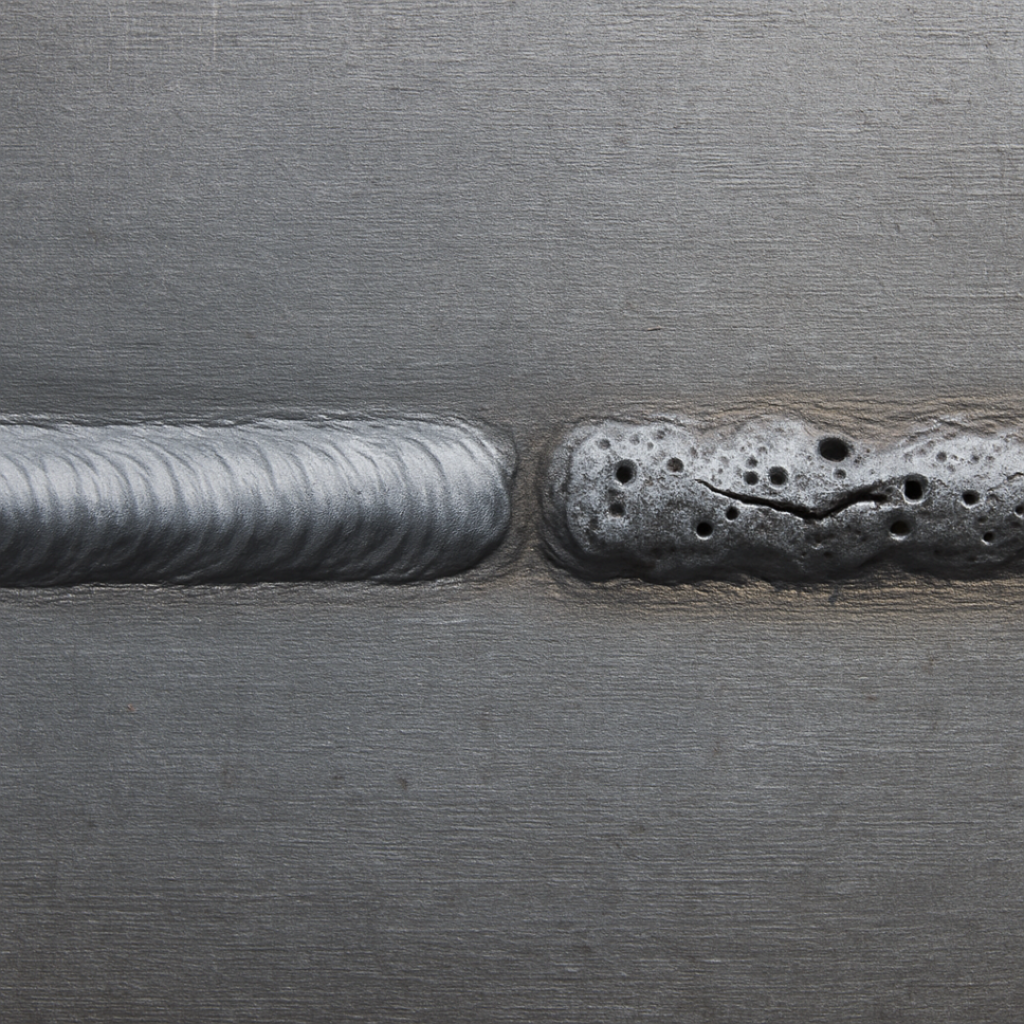
Cracks represent fractures in base metal or weld metal that severely compromise strength, often from rapid cooling, improper filler metal selection, or contamination.
Porosity appears as small holes caused by trapped gas in solidifying weld metal. Moisture in electrodes, base metal contamination, or insufficient shielding gas commonly create porosity.
Slag inclusions occur when slag from previous passes isn’t properly removed before subsequent passes, becoming trapped within weld layers.
Lack of fusion or incomplete fusion happens when weld metal doesn’t adequately penetrate base metal or previous passes, creating voids from insufficient heat or improper technique.
Undercut removes base metal from the joint but fails to fill the groove adequately. Excessive heat, fast travel speed, or improper angles cause this defect.
Overlap deposits excessive weld metal that doesn’t fuse properly into the joint, creating weak connections despite adequate appearance.
Distortion manifests as warping particularly in sheet metal and thin plates from excessive heat causing expansion and contraction.
Burn through results when excessive heat melts completely through base metal or previous passes, leaving hanging pieces on the backside.
Inspection Terminology
Visual inspection examines finished welds for visible irregularities, detecting surface defects through careful observation.
Dye penetrant testing sprays colored penetrant onto welds where capillary action draws it into surface discontinuities, revealing defects through color contrast.
Radiographic testing uses radiation to capture film images revealing internal discontinuities throughout entire weld depth from root to cap.
Ultrasonic testing sends acoustic energy through welds, detecting discontinuities by analyzing sound wave reflections.
A discontinuity describes any irregularity in material uniformity. Not every discontinuity constitutes a defect—only those exceeding acceptable code limits require repair.
Welding Defects and Their Primary Causes
| Defect Type | Visual Appearance | Common Causes | Prevention Methods |
| Porosity | Small round holes in weld | Moisture, contamination, insufficient gas | Dry electrodes, clean base metal, proper gas flow |
| Cracks | Linear fractures | Rapid cooling, wrong filler metal, stress | Preheat, proper filler selection, reduce restraint |
| Slag Inclusion | Dark lines or spots | Inadequate cleaning between passes | Thorough slag removal, proper technique |
| Lack of Fusion | Void between weld and base metal | Insufficient heat, contamination | Increase heat, clean joint, proper technique |
| Undercut | Groove at weld toe | Excessive heat, fast travel speed | Reduce heat, slow down, correct angle |
| Distortion | Warping or waviness | Excessive heat input | Proper sequence, heat control, fixturing |
Advanced Welding Concepts
Heat Management and Technique Terms
Preheat involves heating base metal before welding to slow cooling rates and reduce thermal stress. Post heating maintains elevated temperatures after welding to prevent rapid cooling and cracking.
Stringer bead describes a narrow, straight weld created by moving the electrode straight along the joint. Weave bead involves moving the electrode in zigzag patterns to create wider welds. Multi-pass fillet weld builds up weld size through sequential passes.
Cap completes the weld joint as the final pass. Buttering deposits weld metal to build layers for joining dissimilar metals.
Direct Current Electrode Negative (DCEN) connects the electrode to the negative terminal, creating deeper penetration. Direct Current Electrode Positive (DCEP) reverses connections, creating a cleaning action beneficial for aluminum. Arc blow occurs when magnetic forces deflect the arc from its intended path.
Frequently Asked Questions
What are the basic terminologies in welding?
Basic welding terminology includes bead (the deposited weld line), penetration (depth of fusion), base metal (material being joined), electrode (current conductor), arc (electrical discharge), puddle (molten metal pool), and heat-affected zone (area changed by welding heat). These foundational terms appear in virtually every welding conversation.
What is 1G 2G 3G 4G 5G 6G welding?
These numbers indicate welding positions: 1G is flat, 2G is horizontal (vertical fixed for pipe), 3G is vertical, 4G is overhead, 5G is horizontal fixed pipe, and 6G is inclined fixed pipe at 45 degrees. The letter “G” denotes groove welds, while “F” indicates fillet welds in the same positions.
What does CC and CV mean on a welder?
CC stands for constant current, maintaining steady amperage while voltage varies, used primarily in TIG and stick welding. CV means constant voltage, maintaining steady voltage while amperage varies with arc length, preferred for MIG and flux-core welding processes.
What is AVC welding?
AVC (Arc Voltage Control) automatically maintains consistent arc length by adjusting the distance between the electrode and workpiece. This system compensates for variations in joint gaps or warped materials, particularly useful in automated and robotic welding applications.
What does CFM stand for in welding?
CFM means cubic feet per minute, measuring shielding gas flow rate from the supply to the welding zone. Proper CFM settings ensure adequate weld protection—too little allows contamination while too much creates turbulence that pulls in atmospheric gases.
Mastering the Language of Welding
Understanding welding terminology transforms you from someone who simply melts metal into a craftsperson who communicates professionally, diagnoses problems accurately, and continuously improves technique. This guide covered fundamental terms like beads and penetration, advanced concepts like heat-affected zones, and specialized vocabulary for positions, defects, and inspection methods.
Every term you master opens new doors for learning and professional growth. When supervisors discuss duty cycles, you understand equipment limitations. When inspectors mention slag inclusions or lack of fusion, you know exactly what they’ve found and how to prevent it. When procedures specify DCEP or preheat temperatures, you comprehend the reasoning behind these requirements.
The welding industry’s specialized language initially seems daunting, but consistent exposure and practical application make these terms second nature. Keep this guide accessible as you work, refer to it when encountering unfamiliar terminology, and watch your confidence grow alongside your vocabulary. Whether you’re pursuing welder certification, improving existing skills, or communicating more effectively on the job, fluency in welding terminology serves as your foundation for success.
The American Welding Society recognizes 93 distinct welding and joining techniques, each with nuanced terminology. You don’t need to memorize everything overnight. Focus on terms relevant to your current work, expand gradually, and recognize that even veteran welders occasionally encounter new vocabulary. The key lies not in perfect recall but in understanding concepts well enough to apply them practically and communicate clearly with colleagues who share this fascinating craft.